
8. Attitude Determination, Control, and Sensing
8.6 Sensing
Sensors observe the system to determine attitude and transform these observations into signals that the controller processes. All of us have a built-in attitude-sensor system. As we know from our discussion of the human vestibular system, we use fluid flowing over tiny hairs in our inner ear, along with information from our eyes, to detect changes in our attitude. For example, they sense if we’re standing up or falling over. If we suddenly tilt our head to the side, these sensors detect this motion. If our body violently moves or shakes (such as when we ride a roller coaster), our eyes and inner ear can get “out of synch,” leading to motion sickness. Fortunately, spacecraft don’t get sick from all their rotating, but they do need good attitude sensors. So let’s look at a spacecraft’s eyes and ears.
To understand how sensors help spacecraft determine their attitude, pretend you’re flying the Space Shuttle in low-Earth orbit and need to point the nose at some spot on the surface. You’re in the commander’s seat facing toward the nose. To point the nose at the surface, you must first determine where you’re pointed now. How can you do this? The obvious answer is to look out the window at some reference. Let’s say you see the Sun out the left-hand window. Would this tell you all you need to know? Unfortunately, no. A single reference point gives your current attitude in only two dimensions. In other words, you’d know that the left wing is pointed at the Sun and the nose is pointed perpendicular to the Sun. But the nose could point in various directions and still be perpendicular to the Sun, so what do you do?
To determine your attitude in three dimensions, you need another reference. If you could see some known star out the front window you’d know your orientation with respect to two reference points—the Sun and a star. Knowing the angle between the Sun and the Earth and between a known star and Earth, you could determine how to change your attitude to point the nose at Earth. Let’s look at how we can apply this technique for attitude determination.
Remote Sensing
One important class of attitude sensors works the same way as remote-sensing payloads (on some spacecraft, the payload can actually serve both functions). Recall, to look at a subject, a remote-sensing system must
- Look at it—scan the sensor to point at the subject
- See it—collect EM radiation from it
- Convert it—transform EM radiation into a usable data
- Process it—turn data into usable information
When it comes to remote sensing for attitude determination, three main subjects are available for reference—Earth, the Sun, and the Stars. This gives us three classes of “out-the-window” sensors
- Earth sensors
- Sun sensors
- Star sensors
All these sensors work in pretty much the same way as other remote sensing devices. Typically, they are attached to the spacecraft so the spacecraft must rotate to bring the subject into the sensor’s field of view or rely on “targets of opportunity” that will routinely go in and out of the field of view. Similar to a telescope or camera, EM radiation from the primary subject enters through a lens and focuses on solid state detectors, such as the charged-coupled devices. The sensor’s accuracy depends on how precisely it can discriminate the target, or portion of the target, and how much onboard processing it can accomplish.
Earth/Horizon Sensor

In low-Earth orbit, Earth fills a big portion of the sky. Earth sensors can roughly indicate the “down” direction by simply discriminating where Earth is with respect to the rest of the sensor’s field of view. At geostationary altitude, the angular radius of Earth is about 10°, so a sensor that can find Earth is at least accurate to within that amount. To use Earth as a more accurate method of attitude determination, a sensor must focus only on one small part. Conveniently, sensors can detect Earth’s horizon by focusing on a narrow band of EM radiation emitted by carbon dioxide, CO2, in the atmosphere. These Earth-horizon sensors can be as much as ten times more accurate than a simple Earth detector.
Infrared Earth horizon sensors have recently been implemented for CubeSat attitude determination in the format of a nine-sensor module, achieving a nadir estimation of 0.5° along two axes (pitch and roll) [Nguyen et al.]. Horizon sensors can provide basic 2DOF attitude knowledge with lower mass and cost than star sensors.
Sun Sensor

Sun sensors, the most widely used for spacecraft attitude, are similar in function to Earth sensors. As the name implies, a Sun sensor finds the Sun and determines its direction with respect to the spacecraft-body frame. By their nature, Earth and Sun sensors can give accurate information about attitude in only two dimensions. For example, this means an Earth or Sun sensor can measure pitch and roll relative to the horizon, but not yaw; or pitch and yaw but not roll, etc.
In general, there are three main categories of sun sensor [Curtis]:
- Coarse analog sun sensors: sensors that measure the current output, which is proportional to the cosine of the angle between the sun and the normal to a photocell. The zenith accuracy is seldom higher than around 5° while the accuracy can increase to around 3° for angles from 10-50°.


A number of coarse sun sensors can be mounted into a pyramidal configuration to increase zenith accuracy. Even though these sensors are more accurate and can even have internal redundancy, they are not commonly used on small satellites due to their large volume and high costs.
- Fine analog sun sensors: a translucent window provides a light spot that shifts over the sensing element with changing Sun attitude. The most common implementation of which is using a four-quadrant photodiode.

Fine sun sensors can achieve between 0.005 to 3 degrees of accuracy in 2DOF.

- Digital sun sensors: sensors that operate based on integrating a 2-dimensional light sensor and signal processing, so as to discriminate between direct sunlight and reflected sunlight. Truly digital sun sensors are a much smaller market segment than analog sensors. There are various sun sensors on the market which are advertised as digital, but which are actually analog sun sensors with a digital interface.
Sun sensors are used to initially acquire vehicle attitude from an unknown orientation so that the spacecraft can quickly point toward the Sun to charge. Sun sensors provide coarse attitude data in relation to the star tracker
Star Sensor/Tracker

A more accurate 2-axis reference is a star sensor. Star sensors measure a spacecraft’s attitude with respect to known star locations. Then they compare these measurements to accurate maps of the brightest stars stored in the spacecraft’s memory. The angle between the known star’s position and a reference axis on the spacecraft, θ, then helps determine the spacecraft’s inertial attitude. By using two or more star sensors located around a spacecraft (or by taking multiple measurements with the same sensor), the system can determine its attitude in three dimensions.
The theoretical limit of accuracy for a star tracker depends on [Fialho and Mortari]:
- Stellar distribution around the star sensor, stellar brightness, and attenuation of stellar light by the intervening medium.
- Diameter of the star tracker aperture
- The exposure time of the star tracker observation
For an assumed field of view (FOV) of 90 degrees, 10 cm diameter aperture, and 10 ms observation length, the theoretical attitude error is on the order of 0.01 – 0.1 milli-arcseconds. Arcseconds (denoted by the symbol “) is an angular measurement equal to  of a degree or
  of an arcminute. There are also 206,264.5” in a radian, so that 1” = 4.848 ×
 radians [Swinburne]. All to say that this theoretical limit is very very small: 0.01 milli-arcseconds is 4.8481368
 radians of error!

Realistically, there are many errors that are integrated into the ultimate attitude estimate of a star tracker: sensitivity threshold of the camera, noise in processing electronics, dimensional tolerance of mechanical parts and mounting errors, etc. When all the physical manifestations of error and suboptimal design due to cost or schedule constraints are accounted for, these commercial options have the following attitude error estimates with size, mass, and power for reference [satsearch]. Generally, the smaller the star tracker, the cheaper and less accurate the attitude estimate.
| Model | Vendor | Attitude Error | Size | Mass | Power | Update Rate | Cost |
| ST200 | Hyperion Technologies | < 30 arcsec pitch and yaw
< 200 arcsec roll |
29 x 29 x 38.1 mm | 42 g | 600 mW | 5 Hz | Unlisted, guess magnitude of 1,000 – 10,000 USD |
| CubeStar | CubeSpace | < 55 arcsec cross-axis DE, < 77 arcsec cross-axis RA, <200 arcsec roll | 50 x 35 x 55 mm | 55 g | 142 mW – 264 mW | 1 Hz | ~13,000 USD |
| Star Mapper | New Space Systems | Boresight pointing accuracy 16 arcsec | 136 mm x 136 mm x 280 mm | < 800 g | < 2 W | > 1 Hz | |
| Standard NST | Blue Canyon Technologies | 6 arcsec cross boresight, 40 arcsec about boresight | 10 x 5.5 x 5 cm | 0.35 kg | < 1.5 W | ||
| ST5000 | Northrop Grumman | 0.54 arcseconds in yaw and pitch, 17 arcseconds in roll | Handheld | 10 Hz | 100,000 – 1,000,000 USD | ||
| CT-2020 | Ball | 1.5 arcsec | 5.7” diameter x 12” tall (with
standard sunshade) |
3 kg | <8 W | 10 Hz | “Low-cost” for a large contractor |
| High Accuracy | Ball | 0.14 arcsec | Length of a person | 40 – 100 Hz | Unlisted, assume very very expensive |
In-Situ Sensing
Magnetometer

Another means of measuring attitude directly uses Earth’s magnetic field. A magnetometer is basically a fancy compass that measures the direction of the magnetic field and its strength. Earlier, when we discussed the disturbance torque caused by the magnetic field, we indicated its strength varies with the cube of the radius  and by a factor of two between the pole and equator. By comparing the measured direction and strength of the local field with a high fidelity model of Earth’s field, the sensor can determine the orientation of the spacecraft with respect to Earth. The magnetometer provides the direction and magnitude of the local magnetic field (two axes) to within 0.5 to 3 degrees inaccuracy. Using sophisticated determination and estimation algorithms with only a magnetometer can yield an accuracy of 2 degrees on attitude and 0.01 degrees/sec on angular rates [Carletta et al.].
To see how this works, think about a compass needle. It’s usually just a lightweight magnet that can rotate freely. If you’ve ever played with magnets, you know that one side of a magnet will readily attract and stick to another magnet, while the opposite side will repel it. With magnets, opposites attract and like to repel, so the north pole of a magnet attracts the south pole of another magnet. The lightweight magnet rotating freely in a compass tries to do the same thing. The north end of the compass tends to point at Earth’s North Pole, and suddenly, you’re no longer lost!
The use of magnetometers is limited by the strength of the field, making them more useful in low-Earth orbit than at geostationary altitude. The sensor accuracy depends on the accuracy of the field model. Even so, they offer a relatively inexpensive sensor that can deliver an independent reference from the other sensors we’ve discussed.

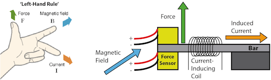
A MEMS magnetic field sensor is a small-scale microelectromechanical systems (MEMS) device for detecting and measuring magnetic fields (Magnetometer). Many of these operate by detecting effects of the Lorentz force: a change in voltage or resonant frequency may be measured electronically, or a mechanical displacement may be measured optically. Compensation for temperature effects is necessary. Its use as a miniaturized compass may be one such simple example application.

Gyroscope
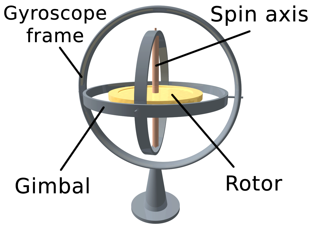
Gyroscopes, like our inner ear, can determine attitude and changes in attitude, directly, without needing to look out the window. The simplest type of gyroscope is a spinning mass. As we know, any spinning mass has angular momentum that is conserved. By using this basic principle, we can use the gyroscope to detect a spacecraft’s angular motion. Two basic principles of gyros make them useful as attitude sensors:
- With no torques, their angular momentum is conserved—they always point in the same direction in inertial space.
- With torque applied, they precess in a predictable direction and the magnitude of angular momentum changes.
When a mass starts to spin, its angular-momentum vector remains stationary in inertial space, unless acted on by an outside torque. For example, let’s spin a gyroscope at 6:00 A.M. with its angular-momentum vector pointed at some convenient inertial reference—say, a star just above the eastern horizon (somewhere to the right side of the page). We can then observe how conservation of angular momentum works to keep the gyro always pointed in the same inertial direction, as long as no torque affects it.

In this case, the angular-momentum vector,  , appears to “track” the star because the star is essentially fixed in inertial space. As the gyro sits in its stand, it looks like it’s rotating throughout the day. Actually, the stand is moving as Earth rotates. The gyro remains stationary in inertial space. Museums often demonstrate this principle with huge pendulums suspended on long cables. The swinging pendulum’s plane remains fixed in inertial space, but as Earth turns, the pendulum’s path appears to move, knocking over dominos spaced around it to the delight of the crowds.
The second basic principle of gyroscopes relates to their strange motion in response to an applied torque. Earlier, we called this motion precession—rotation with constant angular velocity in a direction 90° from the direction of the applied torque.
Knowing these two basic principles, let’s see how we can use a gyro to sense attitude. Because its angular momentum vector stays constant in inertial space, it provides a constant reference for inertial direction. One way to measure rotation with respect to the reference is to isolate the gyro from torques by mounting it on a gimbal (hinged brackets that allow it to rotate freely or that allow the mounting box to rotate freely around the stationary gyro). We then mount the gimbal on a platform in a spacecraft and measure the spacecraft’s rotation by measuring how much the spacecraft rotates with respect to the stationary gyro.
Another way to measure a spacecraft’s rotation is to strap a gyro directly to the spacecraft. Then, when the gyro (or the spacecraft) rotates around an axis perpendicular to the spin vector, the resulting torque will cause the gyro to precess. By measuring this precession angle and rate, the system can compute the amount and direction of the spacecraft’s rotation and thus determine its new attitude.

A moderately new type of gyroscope invented in 1963, called ring-laser gyroscopes, doesn’t use these principles of a spinning mass. They use principles associated with laser light! A ring-laser gyro consists of a circular cavity containing a closed path, through which two laser beams shine in opposite directions (it’s all done with mirrors). As the vehicle rotates, the path lengths traveled by the two beams change, causing a slight change in the frequency of both beams. By measuring this frequency shift, the system can compute the vehicle’s rate of rotation. By integrating this rate over time, it can determine the amount of rotation and hence the vehicle’s new orientation. Ring-laser technology offers similar or better accuracy, with greater reliability than the old style spinning-mass gyros.

The newest type of gyroscope is a Micro-electromechanical systems (MEMS) gyro [Silicon Sensing]. These are packaged similarly to other integrated circuits and may provide either analog or digital outputs. In many cases, a single part includes gyroscopic sensors for multiple axes. These small hemispherical resonator gyroscopes made of quartz glass operate in a vacuum [Wikipedia].

Inertial Measurement Unit

Multiple gyroscopes and accelerometers (or multiple-axis gyroscopes and accelerometers) can be integrated into units called inertial measurement units, or IMUs, to achieve output that has six full degrees of freedom.
How MEMS Accelerometer Gyroscope Magnetometer Work & Arduino Tutorial. By How to Mechatronics.
Today, we typically see MEMs gyroscopes and MEMS magnetometers integrated with a MEMs accelerometer onto a small circuit board for a very low price. By adding the magnetometer into the package, the sensor package is a 9-axis IMU. We already described MEMS gyroscopes and magnetometers. MEMS accelerometers are one of many types of accelerometers; MEMS in the context of accelerometers utilize surface micromachined capacitance. Acceleration is measured through capacitance changed by the deflection of microstructures with an attached mass.

A very wide variety of IMUs exists, depending on application types, with performance ranging [Wikipedia]:
- from 0.1°/s to 0.001°/h for gyroscope
- from 100 mg to 10 µg for accelerometers.
Gyroscope and accelerometer sensors behavior is often represented via a model based on the following errors, assuming they have the proper measurement range and bandwidth:
- offset error: this error can be split between stability performance (drift while the sensor remains in invariant conditions), and repeatability (error between two measurements in similar conditions separated by varied conditions in between)
- scale factor error: errors on first order sensitivity due to non-repeatabilities and non-linearities
- misalignment error: due to imperfect mechanical mounting
- cross-axis sensitivity: parasitic measurement induced by solicitation along an axis orthogonal to the sensor axis
- noise: dependent on desired dynamic performance
- environment sensitivity: mainly sensitivity to thermal gradients and accelerations
High-performance IMUs or IMUs designed to operate under harsh conditions are very often suspended by shock absorbers. These shock absorbers are required to master three effects:
- reduce sensor errors due to mechanical environment solicitations
- protect sensors as they can be damaged by shocks or vibrations
- contain parasitic IMU movement within a limited bandwidth, where processing will be able to compensate for them.
A major disadvantage of using IMUs for navigation is that they typically suffer from accumulated errors. Because the guidance system is continually integrating acceleration with respect to time to calculate velocity and position (see dead reckoning), any measurement errors, however small, are accumulated over time. This leads to ‘drift’: an ever-increasing difference between where the system thinks it is located and the actual location. Due to integration, a constant error in acceleration results in a linear error in velocity and quadratic error growth in position. A constant error in attitude rate (gyro) results in a quadratic error in velocity and cubic error growth in position. Positional tracking systems like GPS can be used to continually correct drift errors (an application of the Kalman filter).
Global Positioning System (GPS)
How Does GPS Work? Video by Sci Bright.
The newest attitude sensor to emerge on the scene is the “differential” Global Positioning System (GPS). GPS is a constellation of 24 satellites in high Earth orbit (12-hour period) designed and deployed by the U.S. Air Force to provide worldwide position, velocity, and time information. Clever engineers figured that by placing two GPS receivers some distance apart on a vehicle and carefully measuring the difference between the two signals, they could determine a vehicle’s attitude. This attitude determination technique may offer a relatively inexpensive, independent system for spacecraft in low-Earth orbits.

Sensor Design Process and Drivers
| Reference | Typical Accuracy | Remarks |
| Sun | 1 arcminute | Simple, reliable, low cost, note always visible |
| Earth | 0.1 degrees | Orbit dependent; usually requires scan; relatively expensive |
| Magnetic Field | 1 degree | Economical; orbit dependent; low altitude only; low accuracy |
| Stars | 0.001 degree | Heavy, complex, expensive, most accurate |
| Inertial Space | 0.01 degree/hour | Rate only; good short term reference; can be heavy, power; cost |
How do we select the best sensors for our needs? Before selecting the sensors [satsearch]:
- Specify your exact mission parameters – ensure you are clear on the full range of activities your spacecraft needs to perform in terms of attitude determination and control.
- Record all known design specifications of the satellite – keep to hand the current specifications of the craft (understanding these may change as the design evolves) – for example, it is vital that sun sensor is correctly accommodated within the spacecraft due to the impact on the system’s ability to use the correct frame of reference.
- Consider the range of technology that will be used in the system – take into account the results of all decisions on what other components and sub-systems have been made. It is important that the sun sensors you choose will work effectively with other components, such as magnetorquers or star trackers in order to establish full attitude knowledge.
- Take into account the key performance criteria – understand how to evaluate available sensor products according to the criteria most relevant for your applications. More on this below.
There are a number of design and performance criteria that dictate the selection of a sensor model:
- Field of view (FOV)
- Accuracy
- Environmental characteristics including operating temperature, radiation tolerance limits, and vibration limits
- Available mass and volume budgets
- Costs
- Update rate (for units with integrated electronics)
- Power consumption
- Angular resolution
Here are tidbits of knowledge that get us closer to a decision:
- Depending on the mission requirements, we need a single sensor or a set of sensors that will give us an attitude estimate, typically in 3 degrees of freedom.
- A star tracker can resolve altitude in all 3 degrees of freedom but is typically very expensive.
- A magnetometer only instantaneously resolves attitude to two degrees of freedom using Earth’s magnetic field but integrated over time can resolve all three degrees of freedom [Searcy]. A sun sensor also only instantaneously resolves attitude to two degrees of freedom using the sun position but can be extended to three axes [NASA JPL]. The two sensor measurements may be combined to determine attitude to three degrees of freedom instantaneously.
- Sensors that measure angular rate or acceleration could help with attitude estimation/determination, such as gyroscopes or accelerometers.
- If we want even more precision, we can combine sensor measurements that overlap in degrees of freedom to get a more precise determination of attitude in 3 degrees of freedom by filtering out noise.
- Configuration constraints
- A sun sensor requires pointing toward the sun to some degree but a star sensor wishes to avoid the sun. Sun sensors and star sensors are typically not mounted on the same spacecraft face and do not face the same direction as they have opposing requirements.
- Inertial measurement units can be strategically mounted close to the center of rotation so that the accelerometer does not measure any centrifugal acceleration. If this is unavoidable, some simple math can cancel out the centrifugal acceleration.
- Magnetometers are typically mounted away from electronics to minimize interference.
Common Configurations
There exist different tiers of ADCS configurations based on available volume/mass and required accuracy/precision:
- Coarse: For even the most mass and volume constrained spacecraft, the 9-axis MEMS IMU achieves an immense amount of coarse attitude information per buck. The direction of the sun can be estimated from the voltage and geometry of the solar panels or photodiodes. Typically, star trackers used to be too bulky and expensive for 1U CubeSats but with recent advancements, the smallest star trackers have a mass of only dozens of GRAMS! That’s incredible miniaturization in progress.
- Small-Satellite Fine: For larger CubeSats that can spare 0.5U to 1U, many vendors offer integrated ADCS packages with controlled/protected structural mounting and algorithms pre-installed/tested. The manufacturer testing and integration can typically guarantee higher accuracy and precision but does cost more due to more engineering hours. Some commercial options include:


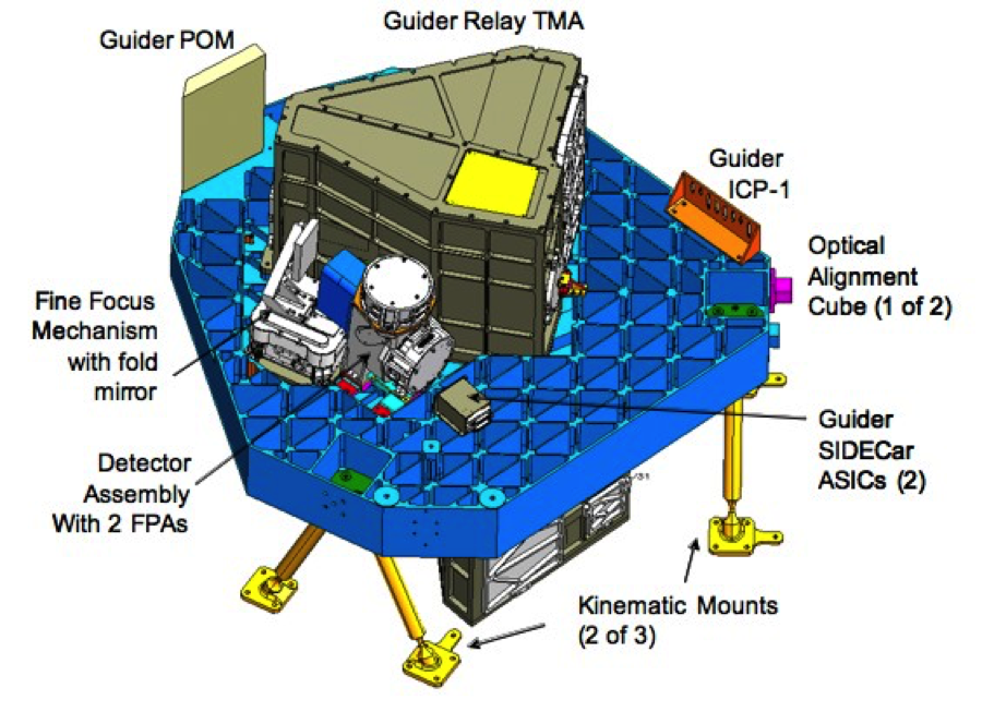
- Flagship Fine: Spacecraft pointing accuracies with sub-arcsec to milli-arcsec levels require all the stops: gyroscopes, accelerometers, magnetometers when relevant, star trackers, sun sensors, and fine guidance sensors (FGS). These large missions have all the components the smaller missions have but allow more volume and mass, resulting in higher accuracy and precision measurements. Small-satellites don’t have fine guidance sensors, which are mission-specific attitude sensors innovated for the unique characteristics of the mission. For the James Webb Space Telescope, the FGS is a near-infrared camera residing in the integrated science instrument module that identifies and acquires a guide star to provide fine pointing data to the ACS for attitude stabilization [JWST]. The ultimate pointing accuracy (with reaction wheel and thruster errors incorporated) is expected to be 0.10 arcseconds!
Artemis Kit Specific
Artemis ADCS Sensors
| Sensor Type | Model | Vendor | Attitude Accuracy | Size
(mm) |
Mass | Power | Update Rate | Cost |
| 9-axis IMU | BMX160 | Mouser | Magnetometer heading 30μT horizontal geomagnetic field | 2.5 x 3.0 x 0.95 | 1 g | 1585 µA @ 1.71 – 3.6 V | 12.5 Hz
3.2 kHz |
6.69 USD |
Acceleration 0.015 m/ |
||||||||
| Angular velocity 0.042 deg/s | ||||||||
| GPS | Venus838FLPx-L | Skytraq | Position accuracy 2.5m CEP
Velocity accuracy 0.1m/sec |
10 x 10 x 1.3 | 0.3 g | 55 mA @ 3.3 V | 1 Hz
50 Hz |
200 USD
|
| Sun Sensor | OPT3001DNPR | DigiKey | 2 x 2 x 0.65 | — | 3.7 µA @ 3.6 V | 10 kHz
400 kHz |
3.05 USD |
