
6. Communications
6.8 Technologies

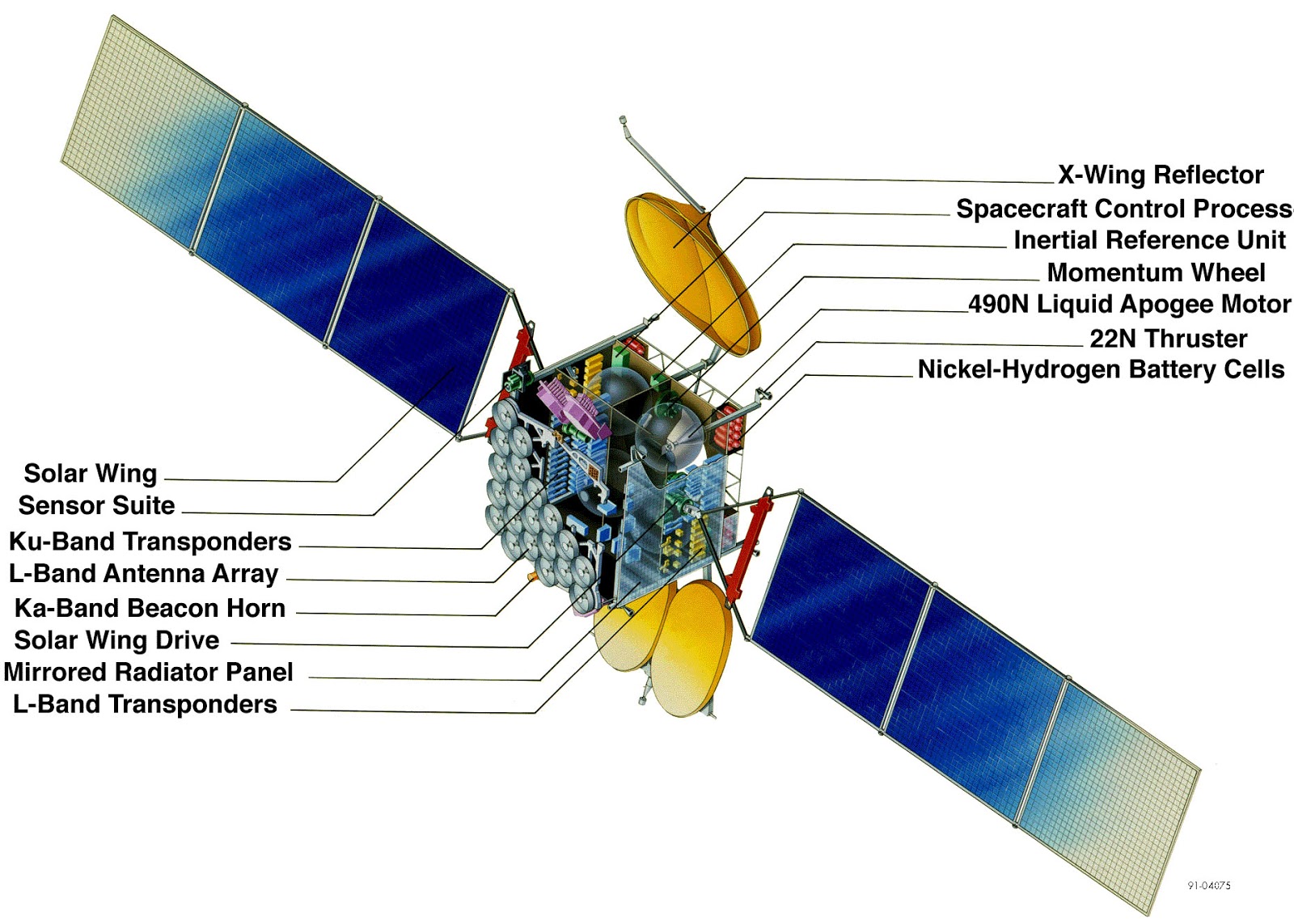
The hardware and software for communications differ on the spacecraft and ground, given the available space and power. Typically, the ground antenna is larger than the spacecraft antenna to increase the gain along with the link budget and there are fewer mass constraints on the ground. The ground antennas also transmit at much higher power for the same reasons, increasing the gain with fewer power constraints. For this section, we will focus on spacecraft technology, like antennas, transceivers, filters, and diplexers.
Antennas

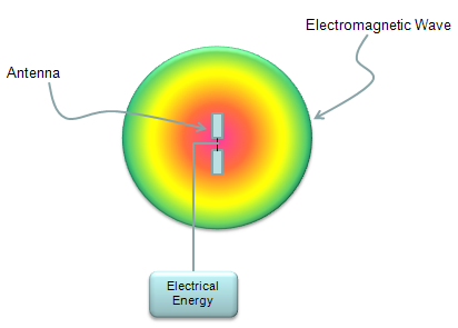
Antennas are circuits (wires, apertures) that interact with EM waves by transforming electrical fields into currents (and vice-versa). Antennas receive & transmit RF (radio frequency) energy. The size/type selected is directly related to frequency/required gain.

There are different types of antennas:


An omnidirectional antenna radiates isotropically in all directions so that the emitted power density at a distance  is:
is:

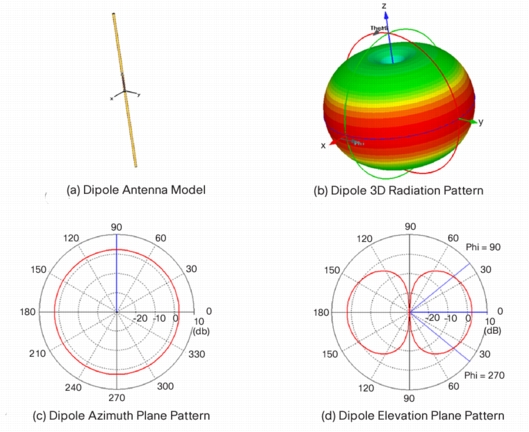
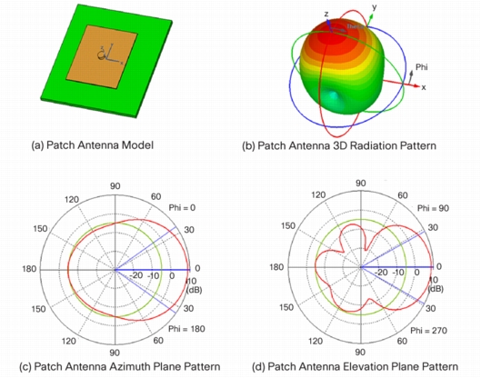
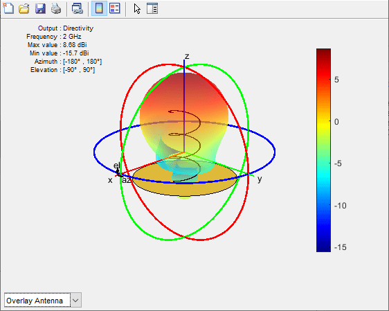
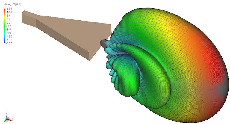
Most antennas are directional, i.e., the intensity of the radiated power depends on the direction.
The gain patterns illustrate the directionality or directivity of the antenna. The directivity of an antenna produces a higher gain in that direction but the satellite must be pointing that axis toward the ground station more precisely to get that improved gain, a trade-off in ADCS complexity.
Transponder/Transceiver

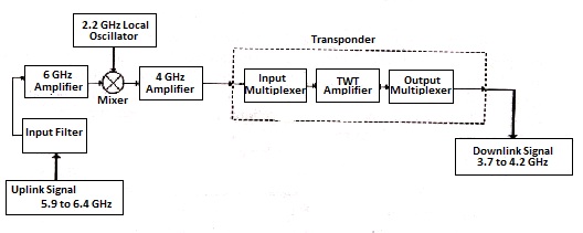
“A communications satellite‘s transponder is the series of interconnected units that form a communications channel between the receiving and the transmitting antennas. It is mainly used in satellite communication to transfer the received signals. A transponder is typically composed of” [Wikipedia]:
- An input band-limiting device (an input band-pass filter),
- An input low-noise amplifier (LNA), designed to amplify the signals received from the Earth station (normally very weak, because of the large distances involved.)
- A frequency translator (normally composed of an oscillator and a frequency mixer) is used to convert the frequency of the received signal to the frequency required for the transmitted signal,
- An output band-pass filter,
- A power amplifier (this can be a traveling-wave tube or a solid-state amplifier).

Diplexer/Multiplexer

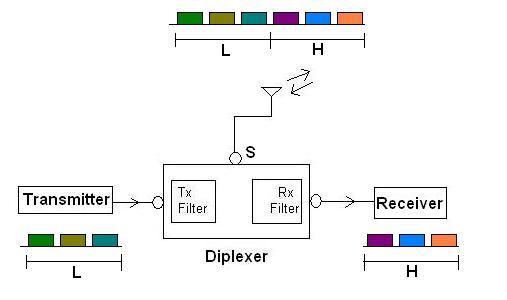
A diplexer “separates two different frequency bands in the receive path and combines them in the transmit path. These frequency bands usually will be wide apart in the frequency domain for the diplexer to work satisfactorily. It is often referred to as RF power combiner/divider with the added functionality of filtering. Broadband Filters are used to pass appropriate bands at Tx and Rx path” [RFWireless]. The multiplexer is the extension to more than two frequency bands.

“There are many different kinds of diplexers. Passive diplexers offer a little more than combiners. They take two signals (one from the satellite and another from the ANT) that won’t interfere with each other and put them on the same cable. Active diplexers add power to the line to limit the amount of loss that happens when signals move through a system. Active diplexers can also shift frequencies so that they work together. When a diplexer does this, the diplexer would also be a modulator” [LemmyMorgan].

Duplex

A duplexers use of the single antenna by both transmitter and receiver parts of a single device or two devices is known as a duplexer. In other words, a duplexer is a device that couples the transmitter and receiver to the antenna while producing isolation between transmitter and receiver. Both transmit and receive paths usually will have frequency bands very nearer, hence narrowband filters are used to separate these frequencies” [RFWireless].

Amplifier
An RF power amplifier “is a type of electronic amplifier that converts a low-power radio-frequency signal into a higher power signal. Typically, RF power amplifiers drive the antenna of a transmitter. Design goals often include gain, power output, bandwidth, power efficiency, linearity (low signal compression at rated output), input and output impedance matching, and heat dissipation” [Wikipedia].

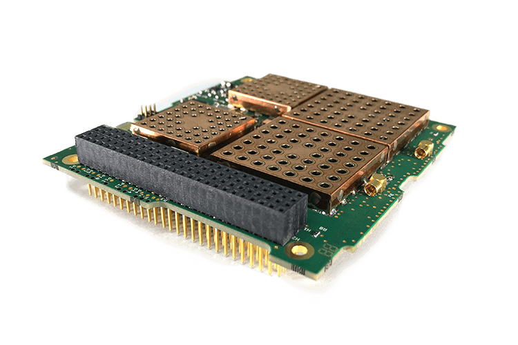
Filter

“Radiofrequency (RF) filters represent a class of electronic filter, designed to operate on signals in the megahertz to gigahertz frequency ranges (medium frequency to extremely high frequency). Such filters are commonly used as building blocks for duplexers and diplexers to combine or separate multiple frequency bands.
Four general filter functions are desirable” [Wikipedia]:
- Band-pass filter: select only a desired band of frequencies
- Band-stop filter: eliminate an undesired band of frequencies
- Low-pass filter: allow only frequencies below a cutoff frequency to pass
- High-pass filter: allow only frequencies above a cutoff frequency to pass


.jpg)