
6. Communications
Hardware Lab for Communications
Communication System Lab: An Epic Adventure in Radios
Purpose:
- Become familiar with basic radio concepts
- Gain experience with the Artemis CubeSat Kit’s communication system
- Validate the kit’s ability to transmit and receive messages
- Have fun sending messages to friends
Background:
Terms to know
- RSSI: received sign strength indicator
- UHF: ultra high frequency (between 300MHz and 3,000MHz)
- FSK: frequency shift keying (you should actually read this one)
- Data rate: measured in bps or bits per second
- Watts: unit of measure for power
- Decibels (dBm): also a unit of power, but in a log scale. Please take note that we can always convert from watts to decibels to use the most convenient system.
- Link budget: in short, how strong does our radio have to be for the Earth to hear its signal
- SPI: digital communication protocol (no need to read this)
Important information:
Our Radio
In the Artemis CubeSat Kit, we have chosen to use to RFM23BPS modular radio. The RFM23 radio was selected primarily because of its low cost and relatively high power output. You can view the specifications download to learn more about the radio!
Our Software
The Artemis CubeSat Kit flight software suite handles all functions on the spacecraft and, as a result, is quite complicated. However, the Comms team has created two small test programs to exercise the radios. These test programs are completely oblivious to the satellite as a whole, they are only designed to operate the radio using the teensy 4.1.

Materials:
For this lab, the class will be broken up into two groups of approximately 10 people. Each group of ten will need the following items. All the items will be provided except for the laptops. Those will be needed to be supplied by the students.
- Two laptops (not supplied to the group)
- The laptops must have the Arduino IDE installed
- Follow these instructions to install Teensyduino
- Two USB -> micro USB cables
- (used to connect our laptops to the teensy)
- Any pair combination of the following
- The Artemis CubeSat kit
- Ideally, this is a complete kit, however as long as the kit includes the teensy connected with a radio and antenna board should work
- The Artemis Comms test kit
- This kit is a bare-bones kit with a populated OBC and Antenna Board
- The Artemis CubeSat kit
Procedure:
Download Arduino IDE
- Visit this site and download the latest Arduino IDE 2.0.X for your machine
- Only one person per team of 5 needs to do this
- Visit this site and follow the instructions to download the teensy boot loader
- Only the people who downloaded the Arduino IDE need to do this
Upload Blink
- Plug in Teensy to computer
- Using the OBC, connect directly to Teensy

A computer connected to Teensy
- Using the OBC, connect directly to Teensy
- The easiest way to ensure your development environment is working is to upload a simple program known as “blink”. Blink will cause the light on the teensy 4.1 to Blink.
- Go to “File” then to “Examples” then to “01. Basic” then to “blink
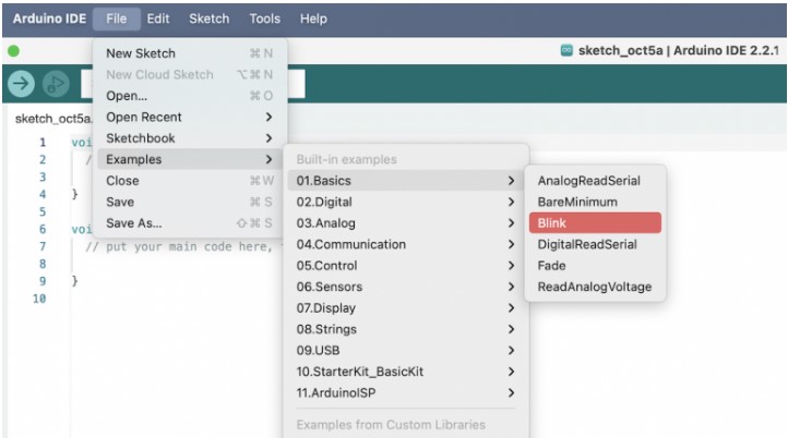
Choosing the “Blink” example - In the top left corner, it will say “select board”
- When you click on select board, you will see USB devices that are connected to your computer
- You may see some ports show up as “/dev/cu.*****” which is labeled as “Unknown” as well as others
- Select the Teensy 4.1
- Otherwise, you can click “select other board and port…” and search for the teensy 4.1

- When you click on select board, you will see USB devices that are connected to your computer
- Upload the program using the right arrow button on the top left corner of the window

- Look at the teensy, if the LED is blinking, then you have successfully uploaded and run the program
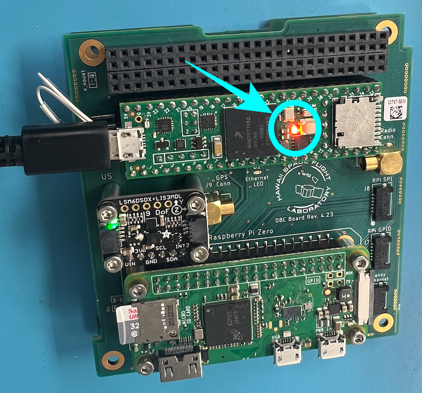
Teensy LED blinking - Practice
- Change the delay times in “blink” to 200
- Note what happens
- Add a print statement
- For example:
- <print(“I blinked”);>
- For example:
- Notice that nothing has changed
- This is due to the fact that we are basically printing to the teensy
- Instead, we want to print to our computer
- This means we need to print to serial (USB)
- Setup serial communication in the blink program
- Add <Serial.begin(9600);> into the void setup() section of the program
- Serial.begin starts serial communication with your computer at 9600baud (bits per second)
- Fix your print statement
- Now that we know we want to print to serial, we can use
- <Serial.println(“I blinked!”);> (or any message you like)
- Make sure your print statement is in <void loop() {>
- Using println adds a return at the end of the line
- Now that we know we want to print to serial, we can use
- Upload your edited program and then open the serial monitor
- The serial monitor can be opened by clicking the magnifying glass in the top right corner
- Now you should see whatever you put in your print statement printed every .4 seconds or so.
- Change the delay times in “blink” to 200


Check-in:
- Indicate that you have the following:
- A teensy that is blinking
- A serial monitor is displaying what you put in your print statement
Assemble the Hardware
- Hardware needed
- OBC with Teensy
- PDU
- Antenna Board (make sure that the Antenna is soldered onto the pad)
- ANT J15 wire
- 2x male to male jumper Cables
- Power supply
- 2x alligator clips
- 1 MCX to MCX cable (for sending setup)
- Micro-USB to USB cable (or whichever your computer uses)

For this part of the lab, you can either have two fully assembled kits, two comms test kits or one kit and one comms test kit. The following instructions is for setting up the bare-bones comms kit (a PDU, OBC and Antenna Board).
1. Place the OBC on top of the PDU and push the headers together. The headers should evenly match up and no extra ones should be showing on any side of the PC104 connectors. This should go together fairly easily. If you feel like you are forcing it take it apart and confirm that everything is aligned properly and try again.

2. Take ANT J15 wire and place the end with the black wire in the third pin slot into the OBC J12 connector.

3. Connect the other end of the ANT J15 wire (the one with the black wire at the fourth pin slot) to the antenna board J15 connector.

4. Insert MCX to MCX cable to OBC J1 (Radio Conn) to the MCX connector connected to the antenna that is being used on the Antenna Board.

- The picture shows the MCX Cable being connected to ANT J13 due to the antenna being used is connected to that connector. If the antenna is attached on the other side connect the MCX cable to ANT J10
CAUTION: Connecting the radio to the Antenna is crucial to keeping the radio functioning. This is required to prevent RF feedback, causing damage to the radio.
5. Next, you will need to plug the two male-to-male jumper cables into the PC104. The first one will be plugged into the top row, 3 holes over from the right end of the board. This is the ground cable. The next one will be plugged in on the top row, 9 holes over from the right side of the board. This will be the power.

6. Connect the power supply to the jumper cables with alligator clips. The ground (black) should be connected to the able three holes from the right and power (red) should be connected to the cable nine holes from the right.

7. Set the power supply to 7.5V and .5A. When turned on, it should read 7.5V and ~.1A. The amps may vary depending on what the OBC board is currently programmed to do.

8. Finally, connect the micro-usb cable to the micro-usb connecter (J17) on the antenna board and plug it into your computer.

- If using the full kit, the batteries should be fully charged and the kit does not have to be connected to the power supply. However, ff the batteries are not inside the full kit, connect through ANT J4 with the power supply. The left wire of ANT J4 is ground while the right side is power. The connection between kit and computer should still be through the micro usb connector on the Antenna Board
Tip: It is easier to use either just a full kit or the components in the barebones kit as described above.
Move onto the next step once the hardware assembly is done and each group has their own setup to use.
Next Step: Get the code
- Open Arduino IDE
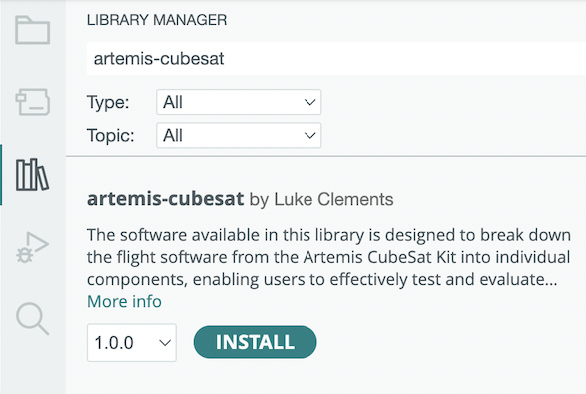
- Click on “Tools” then “Manage Libraries…”
- Search “artemis-cubesat”
- Download Library
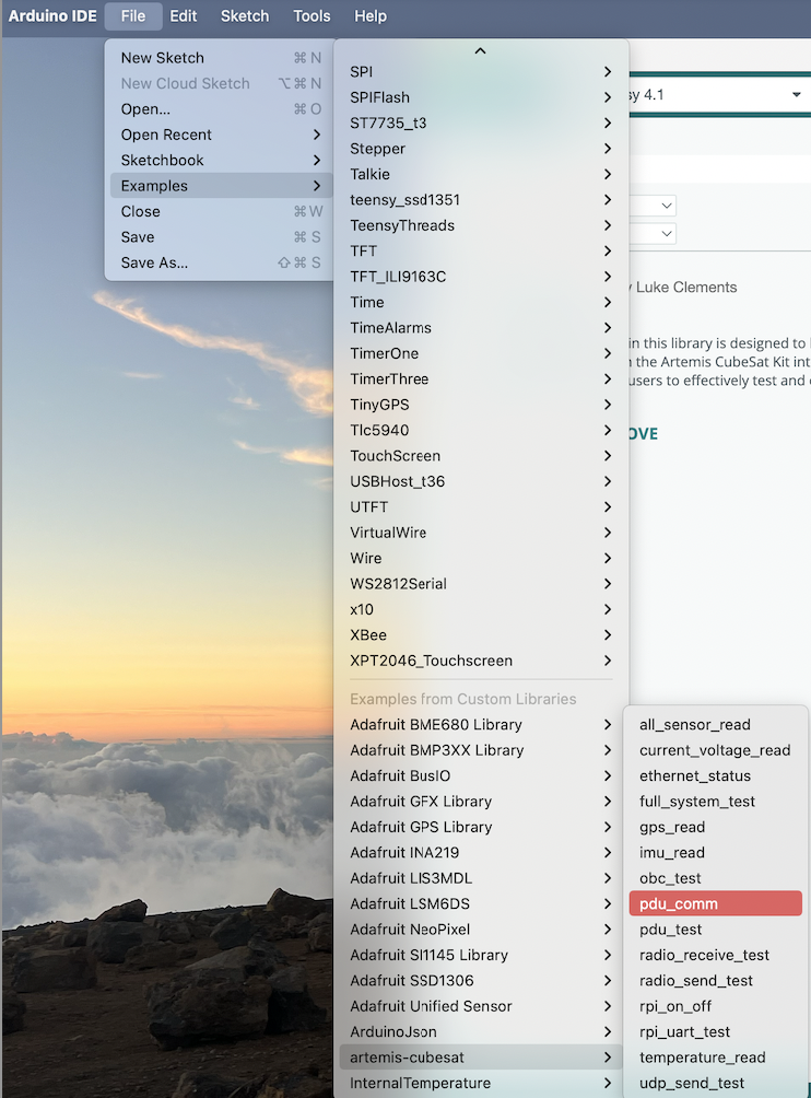
- Now that you have the library, we shall focus on three of the example codes.
- pdu_comm
- radio_send_test
- radio_receive_test
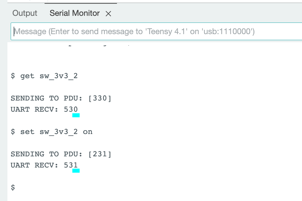
- Give power to the radio by uploading pdu_comm
 In serial monitor type in and enter “set sw_3v3_2 on”
- type and enter”get sw_3v3_2″ to verify if the last digit is 1
- If it is 0, run “set sw_3v3_2 on” until the digit is 1.
- If it is 0, run “set sw_3v3_2 on” until the digit is 1.


Now that the radios are good to go, decide which group will do the sending and which group will do the receiving.
- Receivers:
- Separate yourselves from the sender group
- Make sure to maintain a line of sight from the other group
- In Arduino IDE, click on “file,” “examples,” scroll and find “artemis-cubesat” and then click on “radio_receive_test”
- Separate yourselves from the sender group

-
- As of right now, the code from the artemis-cubesat Arduino Library version 1.0.0 does not have the updated pin number that corresponds with the OBC version that you are using
- Change line 12 in the code from: const int INT_PIN = 8; // 8 on 4.23 //40 on 4.24 or later to const int INT_PIN = 40; // 8 on 4.23 //40 on 4.24 or later (changing the number from 8 to 40)
- Upload the receiver program onto your hardware setup
- Keep an eye on the serial monitor
- When the other team thinks they are sending a message, they will let your team know
- This is when you should expect to see something on the serial monitor
- When you get a message from the other team
- Confirm with the other team that you have received the message
- Write down their message
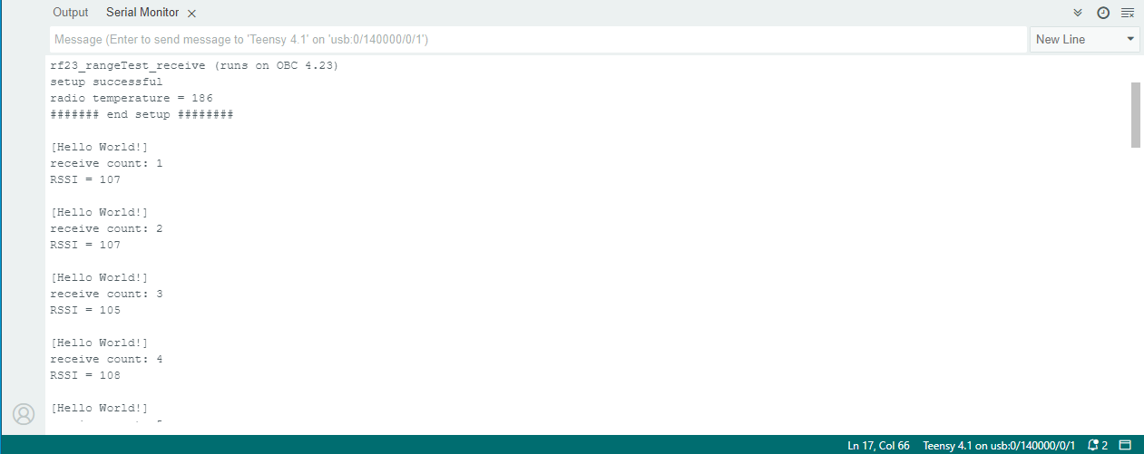
An example of what the receive end would see
- As of right now, the code from the artemis-cubesat Arduino Library version 1.0.0 does not have the updated pin number that corresponds with the OBC version that you are using

-
- Once you have received the whole message, repeat this part of the but from the Senders end
- Senders:
-
- In Arduino IDE, click on “file,” “examples,” scroll and find “artemis-cubesat” and then click on “radio_send_test”
- As of right now, the code from the artemis-cubesat Arduino Library version 1.0.0 does not have the updated pin number that corresponds with the OBC version that you are using
- Change line 12 in the code from: const int INT_PIN = 8; // 8 on 4.23 //40 on 4.24 or later to const int INT_PIN = 40; // 8 on 4.23 //40 on 4.24 or later (changing the number from 8 to 40)
- Look for the <testMessage[]> character array (line 28, right under the cat)
- This is what will be sent over the air to the other group
- Write your own message in the test message
- There’s a 49-character limit on messages
- There is a line that shows you the (approximately) your max message size [I stopped at 45 to be safe]
- If you want to send the other team a long rant about why you like the color green or why Shrek is the best movie from the early 2000s
- Preface the messages with “part x of y:”
- This is for sending messages with multiple parts
- Once you have written your message
- Upload your program to the teensy
- Open the serial monitor to make sure the messages are being sent

- Inform the other team that you have sent a message over
- Your message will send over and over again until you stop the program
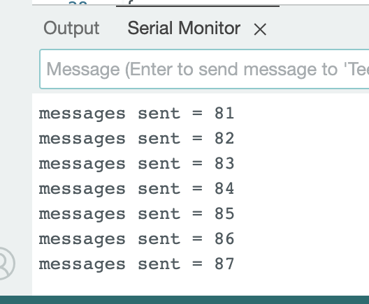
- Your message will send over and over again until you stop the program
- Wait for the other team to confirm that they have received the message
- Once you know the other team got the message
-
- Either switch to Receiver (look at the instructions above)
- Or send the next part of your message
-


The lab is complete after both teams have experienced both receiving and sending messages between the radios. Remember to turn off the power supply after the entire lab is over.
