
5. Power System
Hardware Lab for Power Systems
Power: Introducing the Subsystem Components and Simulating Power Phases
Purpose
- Assemble the subsystem charging circuit and reinforce understanding of the components.
- Measure the state and rate of charge during the phases of the Power System: on the shelf, within the refrigerator, degradation, and charging.
- Measure and compare the charging cycle and efficiency of the Power System.
- Expected X hours of daylight in the orbit and X luminosity from the Sun.
Background and Key Concepts to Consider
Application of: Chapter 5: Power System, 5.1: Definition, 5.5: Power Generation, 5.7: Rechargeable Power Sources
Battery Terminology (via 5.6 Consumable Power Storage):
- Ampere-hour (Ah) – TOTAL CAPACITY OF BATTERY (e.g. 40 Amps for 1 hr = 40 Ah)
- Depth of discharge (DOD) – percent of battery capacity used in discharge (75% DOD means 25% capacity remaining, DOD usually limited for long cycle life)
- % DOD = WhLOADCxVAVG100
- Wh Load = Watt-hours delivered to load = (Load in Watts) (Duration in hours)
- C = Capacity of battery in amp-hours
- VAVG=Average battery discharge voltage
- For long cycle life, DOD may be limited to 50% to 75%
- Watt-hours – stored energy of the battery, equal to Ah capacity times average discharge voltage
- Charge rate – rate Ah which battery can accept a charge. Rule of thumb = Capacity (Ah)/15 hr
- Average discharge voltage – number of cells times cell discharge voltage (1.25 V for most cells)
Artemis Kit Specific
Artemis CubeSat Kit description of the Power System:
The purpose of the Electrical Power System (EPS) is to manage the storage and distribution of power throughout the satellite.
The collection of electrical components handling power distribution is known as a Power Distribution Unit, or PDU. The circuit board holding the PDU is known simply as the PDU board. The PDU board used in this kit is designed by Hawaii Space Flight Laboratory.
In this kit, the EPS subsystem generates power through solar cells and stores them in a battery pack (LG MJ1 18650). The board containing the batteries is known as the battery board, which is designed by PyCubed in this kit. The components for the EPS are:
- Four of 50 Watt-hour Lithium-Ion Batteries (integrated through the PyCubed Battery Board)
- Four Solar Panels, on four out of six faces of the satellite
- Average Power per Panel: .92 Watts
- Regulated Lines (always on): 3.3 Volts, 5 Volts
- Regulated Switched Lines: 3.3 Volts, 5 Volts, 12 Volts
- With attached Solar Cells
Links to the Artemis CubeSat Kit Github: https://github.com/hsfl/artemis
Required Materials & Setup
Artemis CubeSat Components
- Four 50 Wh Lithium-Ion Batteries

- PyCubed Battery board
- Power Distribution Unit (PDU) board


- One Solar Panel

- Electrical Jumper/Dupont Wires (for testing and connecting to pins)

Color is irrelevant, but it is highly recommended to use different colors to allow for easier reference. Lab Equipment
- Multimeter
- AC Bench Power Supply and electrical probes/test leads
- Small, flathead screwdriver
- Lamp/Light for Sun Simulation
- (Electrostatic Discharge) ESD protective mat and antistatic wrist strap (safety)
- Antistatic bags for transporting electrical components
Procedure
Preliminary Lab Procedures


Handling and Connecting the Battery Board
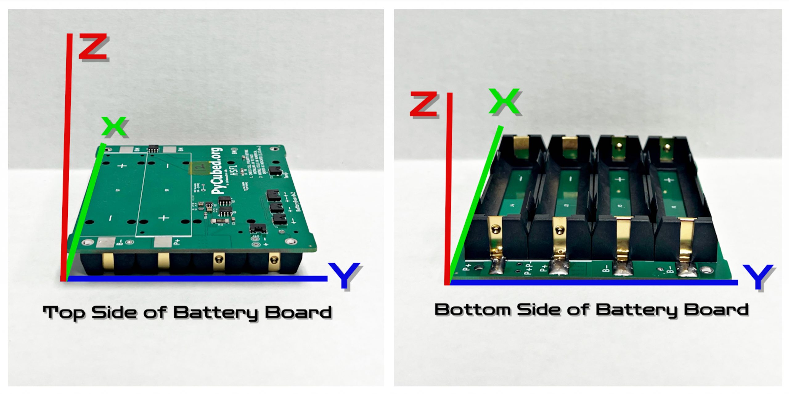
The battery board has two faces, one with four battery slots and the reverse with a much flatter profile. The order in which the batteries are inserted into the battery board is very important. Take note of the different battery slots, labeled consecutively as J1, J2, J3, and J4 on the battery board. Also, notice the positive and negative terminals per battery slot.

The batteries need to be installed in the order J1, J2, J3, and J4. Just like normal household batteries, the positive will go to positive and negative to negative. Insert the positive end of the battery first.

Use gentle force to push the batteries into the slots in the correct order.

**NOTE: When removing batteries, using a small pry tool or pocket screwdriver to gently remove the batteries is the easiest way to do so. Keep in mind not to touch the metal part of the pry tool to the positive and negative terminals of the battery. It will potentially cause a short into the board and a spark that will scare you more than it will hurt. Please be careful!!! **
Use a multimeter on the DC voltage setting to test the voltage across all of the batteries. Probes can be placed on the outer perimeter of the battery slots, on the copper section. Probing at points on the silver solder or on the plastic will not give voltage readings.

Successful testing will give voltage readings on the multimeter.

The batteries are considered “uncharged” around 2.9 V, and the entire battery board will shut off if the voltage reaches that value or lower in ANY of the batteries. Readings across the entire battery board with four batteries inserted may read up to 7.2 V. If batteries alone get readings for voltage but there are no output readings for the board, then the board may be faulty.
PDU Board
- The solar charging circuit is located on the PDU board
- It has a wider voltage range than the previous version and has been proven to work under lamps, sun, and by the power supply
- With maximum light, expect a .03-.04V charge increase in the battery pack every 15 minutes
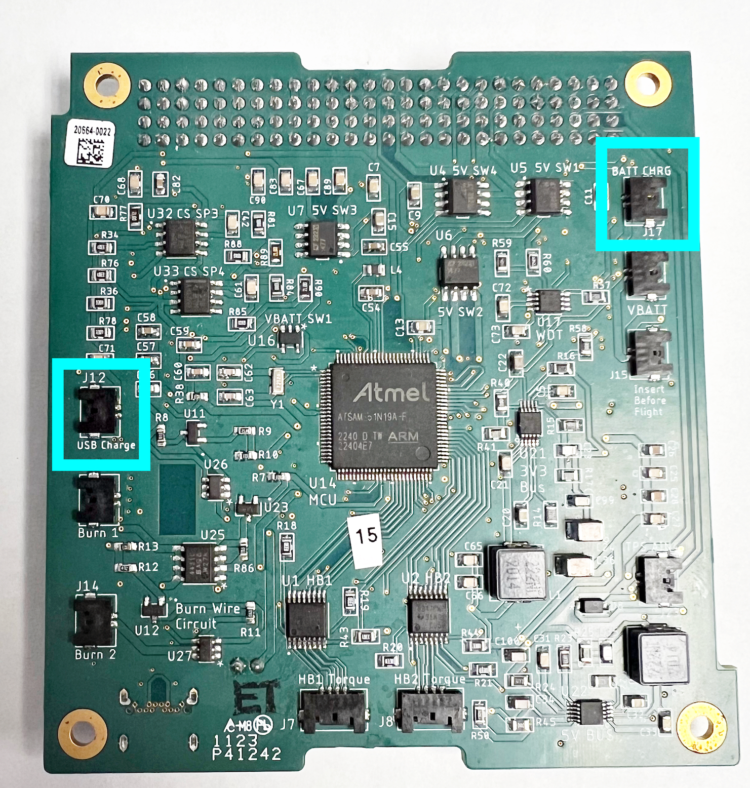
- You will need to connect to three connectors on the PDU
- Inhibit Switch (J18, bottom left of top of board) – closes the solar charging circuit allowing the batteries to charge. Without this connected, the solar charging circuit will not work.
- Solar input (J12, left side of bottom of board) – USB charging
- Battery Charge (J17, top right of bottom of board) – attach batteries to this connector.


Using a power supply, I would recommend using 7.5V and .5A. The circuit can take more voltage, however, the batteries draw a large amount of current from the power supply when over 8v.
Put the PDU J18 connector into J18. This will close the solar charging circuit and allow power to flow to the batteries.

Place 2 pin to stripped wire connector into J12 of the PDU board.

Connect BBJ9 wire to J9 on the battery board.

Connect BBJ10 to the battery board J10. This will close the circuit on the battery board and allow power to flow to or from the batteries. Without this connector, the batteries cannot be used.

Connect either end of BBJ9 to J17 on the PDU.

Now connect a power supply to the wire coming out of J12 (USB charge) of the PDU. Power should be connected to the top pin and ground connected to the bottom pin.

Measure the battery voltage at the test points on the battery board.

Set the power supply to 9V and .5 amps. Turn on the power supply and measure the voltage coming out of the batteries at the same points while the power supply is on. The power supply should be showing from .2 to .4 amps at 9V. The lower the original battery voltage, the higher the amps. The battery voltage should increase from .05 to .2 volts.

Handling and Connecting a Solar Panel
The satellite will use Solar Panels on the outside structure to charge the batteries in space. For this tutorial, one solar panel will be connected to the PDU board and battery board to demonstrate how the system will charge in space.
Just like the PDU board, the solar panel has a negative and positive point/hole(s) for testing and powering purposes. There are two locations at the corners of the solar panels to test. During this testing, it is irrelevant which ones you choose to use, just keep in mind the positive terminal is the hole with the black line traced around it, while the negative is the adjacent, plain hole.

Keeping in mind the positive and negative on the board you want to now test with the corresponding leads on the multimeter in the DC voltage setting.

Using the multimeter and a good working board, readings will approximate 2.7 V. Measurements will vary from board to board and depending on the light environment you are testing in.

To see the difference between indoor lighting and outdoor lighting, you can now test your solar panel in the sunlight. Test the solar panel exactly the same way with a multimeter after taking it outside. You will notice by just being in the sun briefly, the voltage will increase. Measurements will vary from panel to panel and your testing environment’s lighting.

Connecting the Solar Panel to the PDU Board
- Connect the solar panel board to the PDU board
- Using the wire SP1J2, connect the four-pin side to the solar panel J2 and the two-pin side to the PDU J1
- Also, connect PDU J18 to the PDU J18 connector

- Connect the battery board to the solar panel board
- Using wire BBJ9, plug the four-pin end into the battery board J9 and one of the two-pin ends into the PDU J17
- Also, connect BBJ10 to the battery board J10

The circuit is now ready for solar charging.
- Place the solar panel towards the sun and measure the initial voltage.
- Place the negative end of the multimeter on any negative end on the battery board.
- Place the positive end on the same cell holder positive end that the negative end is placed on.

Now we wait……………………
- 10-15 minutes should be enough to see some change.
- Every 15 minutes the battery pack will be charged .03-.04 volts with maximum light.
Main Lab Procedure
Testing the Charging Circuit
Charging the Batteries via Solar Power
- Charging under ambient light vs. outdoors, reading battery voltage levels using a multimeter.
Simulating the Phases
(Setting up the area for the lamp and charging battery/solar panels. Measure the state and rate of charge per phase. Depending on the time for each phase, scale the lab time accordingly or try to have different “stations” set up with each kit, so groups only have to rotate around and share data.)
- A battery’s state of charge or percent of total capacity discharged = est. by measuring the voltage of a cell
- Analog to Digital converter on an onboard computer or battery board
- For lithium-ion batteries, the voltage for a significant portion while discharging can read the same voltage level, which makes determining the true capacity difficult and potentially inaccurate.
- Estimating the state of charge is very difficult due to but not limited to nonlinearity with respect to voltage, hysteresis, or memory effects due to the previous cycling, variation to temperature, and on. Today, algorithms for estimating the state of charge are state-of-the-art research, utilizing advanced techniques such as machine learning techniques.
On the Shelf Phase
Within a Refrigerator Phase
- Refrigerators mitigate the effects of self-discharge
- Household refrigerator or freezer
Degradation Phase
- Self-discharge
Charging Phase
- With sun lamp, to charge the panels
Clean Up
(Turning everything off, disconnecting everything, making sure it’s done safely!)
Lab Review and Deliverables
- Comparisons here! Ask about expectations vs. reality. What is the efficiency/error when compared?
Safety and Best Practices Tips
- Workbenches must be clear of paper and other debris, preventing debris from contaminating the electronic board(s) and potentially short-circuiting the exposed circuitry, especially metal shards.
- When working with electrical components, it is best to place them atop a (grounded) ESD protective mat and wear an antistatic wrist strap.
- When transporting ESD-sensitive components you should place them in antistatic bags.
- As a precaution, electrical components should be connected in order of positive to negative and reversed when disconnecting.
References and Other Work
Artemis Kit Specific
Artemis Power Budget
Power Budget – Typical Mode Sequence Summary
** need efficiency and estimates
| Settings | |
| Parameter | Value |
| Time Step (min) | 1 |
| Max Charge (Wh) | 29.6 |
| Min Charge (Wh) | 0 |
| Min Safe Charge (Wh) | 5.92 |
| Initial Charge (Wh) | 29.6 |
| Results (24 Hours) | |
| Parameter | Value |
| Lowest Charge (Wh) | 29.24 |
| Highest Charge (Wh) | 29.60 |
| Average Charge (Wh) | 29.52 |
| Highest Discharge Rate (W) | 0.65 |
| Highest Charge Rate (W) | 3.25 |
| Average Power Usage (W) | 0.70 |
| Average Power Generated (W) | 1.81 |
| Results (First Orbit) | |
| Parameter | Value |
| Lowest Charge (Wh) | 29.25 |
| Highest Charge (Wh) | 29.60 |
| Average Charge (Wh) | 29.52 |
| Highest Discharge Rate (W) | 0.64 |
| Highest Charge Rate (W) | 3.24 |
| Average Power Usage (W) | 1.03 |
| Average Power Generated (W) | 1.77 |
Artemis Kit Specific
Artemis Requirements
All cells and batteries on the CubeSat shall adhere to the design and testing requirements for spacecraft flight onboard or near the ISS as derived from the NASA requirement document JSC 20793 Crewed Space Vehicle Battery Safety Requirements.
3.1 The CubeSat power system shall generate power in LEO and provide sufficient power to all other bus components
3.1.1 The solar panels shall generate a minimum of 2.5W to charge the battery
3.1.2 The power distribution system shall supply sufficient power to all the other subsystems
3.1.3 The battery shall have a capacity of at least 10Wh
For our system, we have the following:
- power generation requirement of 2.5 W,
- solar cell selection of ANYSOLAR’s SolarBITs with 25 % efficiency,
- solar irradiance at Earth, I0 = 1360.8 W/

- incidence angle across all solar arrays, qi= 54.7 degrees
The total surface area across the 3 CubeSat faces is 30,000 mm^2. The solar cells need to cover at least 42 % of the CubeSat faces to satisfy the 2.5 W power generation requirement. Each solar cell has a surface area of 23 x 8 [mm] or 184 mm^2 with a mass of 0.5 grams. We need at least 69 cells to meet this requirement or 23 cells per face. To cover 5 available faces, the entire CubeSat will have 115 solar cells with a total mass of 57 grams, or about 5 % of our mass budget.
A =  * cos(54.7 deg) * 0.25 = 0.0127 or 12,724
A=(2.5W) (1360.8W) cos(54.7deg)(0.25)= 0.0127 or 12,724
- Each cycle is an interval between the charge (charge current 1,020mA) with 100mA cut-off and the discharge (discharge current 3,400mA) with 2.65V cut-off. Capacity after 500 cycles.
- Capacity ≥ 2,010mAh (60% of Standard Capacity)

Artemis Kit Specific
Artemis Battery Sizing
To determine the number of battery cells that must be in the spacecraft, we must define the maximum load and duration from the spacecraft system power budget and profile, and the DOD and average voltage are from the battery specifications.
- The maximum load of the Artemis CubeSat occurs during the Data Transmit mode at 3.29 W.
- The duration of this mode lasts for 4 minutes.
- The DOD from the selected battery is conservatively 50%.
- The average, nominal voltage is 3.6 Volts.
- Total Capacity Requirement = (3.29 W * 0.0666 hr) / ( 0.5 * 3.6 V ) = 0.122 Amp-hr
- Battery Capacity Requirement = 0.122 Amp-hr * 3.6 V = 0.438 W-hr
- A single battery cell offers 3.35 Amp-hr, more than satisfying the total capacity requirement. Additionally, the Artemis CubeSat Kit offers 4 cells in the battery pack to accommodate more power-hungry payloads.
