
4. Structures and Mechanisms
Structures and Mechanisms Lab
Structures – Assembly and Load Analysis
Purpose
- Assemble the frame of the satellite
- Validate structure size/fit check requirements in mock 3d-printed deployer model and measurement with instrumentation
- Verify and measure the mass of the structure, compare to mass budget and maximum mass requirements of 1.33 kg
- Validate the structure’s ability to sustain the applied compressive load of 1200N (approximately equivalent to 269.8 lbf)
Background and Key Concepts to Consider
Application of: General Arrangement and Design Drivers (Mass, Structural Loads, Materials) and Structural Analysis.
Artemis CubeSat Kit description of the Structure:
- 1U CubeSat, Custom Designed Aluminum Structure
- Material: Aluminum 6061 T6, hard anodized
- Outer Dimensions: 100.00mm x 100.00mm x 113.5mm
- Approximate Mass: 150 grams
- Screw Fasteners: 316 Stainless Steel
- The structure and mechanisms of this kit are designed to follow Nanoracks and Cubesat Launch Initiative (CSLI) requirements. See the References section for the full list of requirements.
Links to the Artemis CubeSat Kit Github: https://github.com/hsfl/artemis
Required Materials & Setup
- From kit: Artemis CubeSat Kit structure frames
- Bottom Plate
- Top Plate
- Two (2) Side Plates
- Eight (8) Structure Screws: 5 mm long M2 screws (link)
- 316 Stainless Steel Hex Drive Flat Head Screws. 90 Degree Countersink, M2 x 0.40mm Thread, 5mm Long.
- 2mm, M2 Hex Screwdriver
- Length Measuring Device for fit check (e.g. ruler, caliper, mock-up of deployer model)
- Flat, thick surface to stand on structure with, like a textbook
- Weights, to supplement anything needed
Scales to figure out unknown weights (e.g. kitchen scale for measuring the structure mass, luggage, or bathroom scale for loading test)


Procedure
Preliminary Lab Procedures
Optional: 3d print the deployer mock-up for a fit check
- 3D print files (public link)
Main Lab Procedure
Assembly of the Frame
The bottom plate of the structure frame is the base. Place the bottom plate down with the protruding cubed feet of the rails on the working table. Take a side piece and gently align and slide them onto the base of the frame. Start with one plate, and use the table as a guide when sliding on the side plate to the bottom plate.

Make sure the two bolt holes for the side plates and solar panels line up between the bottom plate and each side plate. The outer hole with a countersink will be used to secure the frame side pieces to the bottom plate, as it will allow for the bolt to sit flush. Use two screws to fasten the first side plate to the bottom plate.
Important: The screw should easily be inserted and screwed in, not forced. If it seems like the screw needs force to be screwed in, try and readjust it. Forcing the screw in can result in the threading of the holes being stripped and ruined. Screws do not need to be over-screwed/very tight, a small twist with the screwdriver should be sufficient once the screw becomes flush with the rest of the structure.

After attaching both side plates to the bottom plate, the frame is three-quarters of the way assembled with just the top plate missing. A total of four screws will be fastening both of the side plates to the bottom plate, and be flush with the face of the outside surface of the satellite.

Now, all that should be remaining will be the top plate. This piece will be attached to the top of the structure that has been completed so far. The top plate may need to be gently pushed onto the rest of the frame, but not forced on. The holes on the top section and bottom section are keyed. This means they are not symmetrical and will only align in a certain orientation. Note the orientation of the bottom section holes and align the top section holes. Also take note of where the bolt holes are and line them up the same way as the bottom plate, allowing the bolts to align flush with the frame. This is important so that the rest of the frame will be assembled properly and allow for the solar panels to be attached later on. With the top plate attached, the remaining four screws should be used to secure the entire frame together. Again, screws do not need to be over-screwed, a small twist with the screwdriver should be sufficient. This completes the frame assembly!

Mass and Fit Check

Loading Test
A simple loading test can be performed by compressing the structure underweight similar to the force expected during launch, 1200 N or approximately 269.8 lb/f. This force is designed for the structure made of Aluminum 6061 T6 in the Z direction. Note: If the structure is used in the procedures is NOT made of Aluminum 6061 T6, this loading will NOT be the same.
For this lab, a fun and easy way to do this is to have a person stand on the structure, then supplement the remaining weight with everyday objects to reach the target weight as close as possible. After reaching the target weight, check how the structure performed and if any fractures or failure points have appeared. Other creative methods may also be used to conduct a simple loading test as well! The procedures will outline the suggestion of having a person stand on the structure with assistance from others.
Loads using a Human and Everyday Object’s weight
Before getting started, be sure to use safety precautions and assist as needed to keep the demonstration and participants safe at all times! Select a volunteer(s) that will stand on the CubeSat structure to apply the load. If possible, two people may stand on the structure!
Estimate the volunteer’s weight and supplementary weight that will be needed in addition to the volunteer standing on the structure. Again, the goal is to get as close as possible to loading the structure with the target weight. If additional weight is needed, gather materials to supplement the weight.
- If using a kitchen/bathroom scale, find the volunteer’s weight first without weighing anything else. Then, use the box(es)/bag(s) as needed to hold additional weights and measure them on the scale (or have the volunteer hold the additional weights and take the difference of the total weight and the volunteer’s weight if it’s too light on its own).
- If using a travel scale, use a bag to hold the additional weights and weigh the bag that the volunteer will carry on them when standing on the structure.
- In the example case of those who prepared this demonstration, the volunteer was 150 lbs. The supplemental weight of 110 lbs was prepared by using textbooks and backpacks. A total of 3 bags were to be carried by the volunteer, plus a stack of textbooks in the volunteer’s hands.
Once the approximate weight that will be applied is known, prepare to load the structure. Place the structure on flat ground. It is important that the structure is sitting with the rail feet pointing up and down, and not the other way with the rail feet pointing to the sides!

It should also be in an area that will be relatively safe in case anyone were to lose their balance and they or other lab mates can help catch their fall by using nearby, sturdy objects like a table or bookshelf, or by standing near the volunteer, respectively. Using something thick and flat for the volunteer to stand on the structure is highly recommended.
The volunteer should carefully step onto the structure. It’s recommended to step on with one foot first while using supports to prevent falling. Once the volunteer has one foot on the structure and feels comfortable, they can continue to bring their second foot and full weight onto the structure while staying supported. If possible, their feet should be close together when first stepping onto the structure, but shifted/pivoted outwards so they stand wider and feel more stable standing on the structure on their own. Remember to stay safe and take precautions or stop the demonstration if participants do not feel comfortable with their safety!
If additional weights are going to also be added, be sure to slowly give them to the volunteer to hold (in their arms, or on their body if weights are in a bag) and make sure they are supported while doing so, in case they lose their balance. Try to distribute the weight that they carry evenly, so they have an easier time keeping their balance on the structure.
After the target weight has been reached, the structure has been loaded to the approximate force! Carefully remove the weights and help the volunteer safely step off of the structure. Check the structure for any damage or fractures!
Video example of the loading procedure.

Clean Up
Disassembly
Use care when unscrewing and taking apart the pieces of the structure. Turning counterclockwise from the top of the screw should loosen it, while turning clockwise tightens. Having a tray or box to place the disassembled pieces may be helpful in keeping things organized and preventing the loss of screws.
Loading Test
Carefully remove the weights and help the volunteer safely step off of the structure. Remove weights in an order that will help the volunteer keep their balance best, and make sure they have supports to lean on in case they lose their balance.
Lab Review and Deliverables
- What were the outer dimensions of the assembled satellite frame?
- What was the measured mass of the assembled satellite frame?
- How much weight and stress was applied to the structure in the loading test?
- What is the factor of safety of the structure? How much weight could the structure theoretically support?
Safety and Best Practices Tips
- Be careful of stripping screws/threading when screwing in the fasteners. Do not use too much force and make sure the screw is aligned before fastening.
- Ensure the structure frames are assembled correctly by matching the screw holes for each frame piece together. Screws used for the structure should be fastened into the holes with the countersink, so the screw head is flush with the surface of the structure and does not stick out once it is screwed in.
- When tightening screws, wait (if needed) until several screws are in place before making it very tight.
- When working with small parts, it is recommended to work in a clean, tidy space, or use a tray to keep the pieces from rolling off the table.
Alternative Activities
- What other structural tests are expected for a CubeSat?
- How much weight is left for the rest of the satellite components?
References and Other Work
See the Reference Documents section in Chapter 4.6 Structural Analysis for the full list of specifications and requirements.
Artemis Kit Specific
Artemis Requirements
| 3.6 | The CubeSat structure shall be contained within 1U and offer flexibility in mounting components internally | |
| 3.6.1 | The CubeSat kit structure shall remain inside a 10 x 10 x 11.35 cm +/- 0.1mm volume while undeployed | |
| 3.6.2 | All four protruding corners on the top and bottom of the main body of the CubeSat shall not exceed a height of 6.75mm, shall have a minimum length and width of 6mm, and shall have a surface area of 6.5mm x 6.5mm, per NASA CLSI requirements | |
| 3.6.3 | There shall be a minimum of 20mm from the CubeSat surface to the top of the corners along the Z direction per NASA CSLI Requirements | |
| 3.6.4 | The four edges of the CubeSat along the Z direction shall have a hardness greater than or equal to Rockwell C 65-70 per NASA CSLI Requirements | |
| 3.6.5 | The overall structure shall withstand 1200N between two XY planes applied in the Z direction, per NASA CSLI Requirements | |
| 3.6.6 | The maximum mass of the entire CubeSat Kit shall not exceed 1.33 kg per NASA CSLI Requirements | |
| 3.6.7 | The center of gravity shall be within 2cm of its geometric center relative to the Z direction, per NASA CSLI Requirements | |
| 3.6.3 | The CubeSat kit shall be easy to assemble with the provided instructions |
CubeSat Mechanical Specification from Nanoracks
- The CubeSat shall have four (4) rails along the Z-axis, one per corner of the payload envelope, which allow the payload to slide along the rail interface of the NRCSD as outlined in Figure 4.1.1-1.
- The CubeSat rails and envelope shall adhere to the dimensional specification outlined in Figure 4.1.1-1.
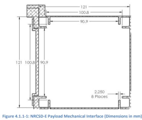
- Each CubeSat rail shall have a minimum width (X and Y faces) of 6mm.
- The edges of the CubeSat rails shall have a radius of 0.5mm +/- 0.1mm.
- The CubeSat +Z rail ends shall be completely bare and have a minimum surface area of 6mm x 6mm.
- The CubeSat rail ends (+/-Z) shall be coplanar with the other rail ends within +/- 0.1mm.
- The CubeSat rail length (Z-axis) shall be the following (+/- 0.1mm):
- 1U rail length: 113.50mm
- 2U rail length: 227.00mm
- 3U rail length: 340.50mm
- 4U rail length: 454.00mm
- 5U rail length: 567.5mm
- 6U rail length: 681 to 740.00mm
- The CubeSat rails shall be continuous. No gaps, holes, fasteners, or any other features may be present along the length of the rails (Z-axis) in regions that contact the NRCSD-E rails.
- The minimum extension of the +/-Z CubeSat rails from the +/-Z CubeSat faces shall be 2mm.
- The CubeSat rails shall be the only mechanical interface to the NRCSD-E in all axes (X, Y, and Z axes).
- The CubeSat rail surfaces that contact the NRCSD-E guide rails shall have a hardness equal to or greater than hard-anodized aluminum (Rockwell C 65-70).
- The CubeSat rails and all load points shall have a surface roughness of less than or equal to 1.6 µm (ISO Grade N7).

Mechanisms: Burn Wire and Deployer Demonstration
Purpose
- Demonstrate and validate the ability to deploy antenna
- Validate the importance of redundant deployment switches
Background and Key Concepts to Consider:
- Application of: 4.5 Mechanisms – EPET 400: Spacecraft Mission Design
- Artemis CubeSat Kit description of the onboard mechanisms:
- Deployable “tape measure” antenna
- Burn wire scheme using nichrome wire and fishing line
Links to the Artemis CubeSat Kit Github: https://github.com/hsfl/artemis
Required Materials & Setup
- Artemis CubeSat structure (frame-only assembled)
- See the instructions for how to assemble in the Structure hardware lab section.
- The structure assembly can be done with the preliminary procedures before moving on to the main procedure for this lab.
- Structure fasteners for antenna board
- Eight Hex Drive, M2 x 0.4 mm Thread, 8 mm Long, 18-8 Stainless Steel Low-Profile Socket Head Screws
- Eight M2 x 0.4 mm Thread, 18-8 Stainless Steel Hex Nuts
- 90 Degree Countersink, M2 x 0.40mm Thread, 5mm Long, 316 Stainless Steel Hex Drive Flat Head Screws
- To assemble the structure frame if not already assembled

- Antenna board

- Antenna

- Antenna fasteners

- 2mm, M2 Hex Screwdriver
- Phillips Screwdriver
- AC Bench Power Supply and electrical probes/test leads
- Nichrome wire, 30 to 32 gauge
- Fishing line, 20 lb
- Soldering helping hands
- Clippers/scissors
- Electrical Jumper/Dupont Wires (for testing and connecting to pins)
- Multimeter
- ANT J4 wire
This portion of the lab requires:
- Antenna board
- Antenna
- Connector ANT J4
- Assembled structure
- Power supply
- Alligator clips
- Fishing line

- Insert the male Molex connector of the ANT J4 wire into the female Molex connector J9 of the antenna board


- The antenna board and connector should look like the picture below.

- Attach the antenna board to the structure. You will use 8 screws to screw the antenna board to the top of the structure. This will secure the board and the structure for when the antenna deploys. As seen below

- Tie the fishing line to the hole of the antenna and leave enough fishing line on the end to wrap it around the structure. Any standard knot should do.

- Wrap the fishing line around the structure to have tension on the antenna. The fishing line and antenna should look like the picture below.
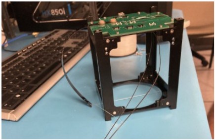
The fishing line is wrapped around the CubeSat structure. - Tie the fishing line to the burn wire. Again, any knot should do.


- Connect ANTJ4 to the power supply.
- Connect the alligator clips to the ANT J4 wire.
- Orient the antenna board so that the wires are pointed straight down. The wire on the left should be connected to power while the wire on the right should be connected to the ground.
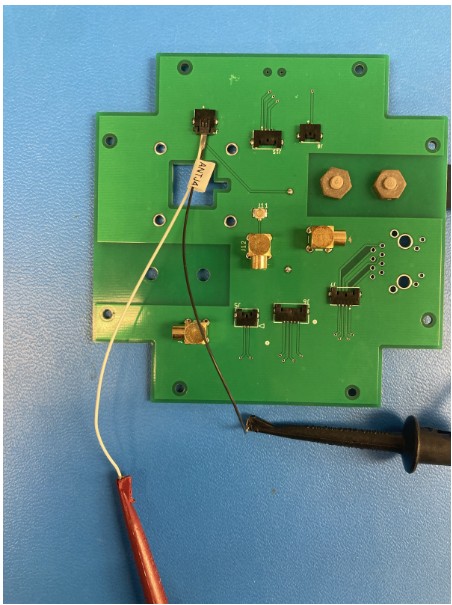
Ground and Power alligator clips secured to the end of the ANT J4 wires.
- Orient the antenna board so that the wires are pointed straight down. The wire on the left should be connected to power while the wire on the right should be connected to the ground.
- Below is what the whole configuration should look like.


- Set the power supply to 5 volts and 2 amps the fishing line will burn off. Turn off the power supply after the fishing line burns or after 15 seconds. Whichever one comes first.
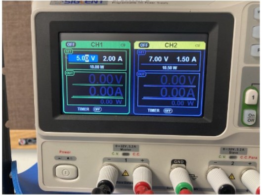

- No need to reconnect the fishing line but set the power supply to 5 volts 3 amps. Turn on the power supply for 10 seconds.

- Observe the burn wire.
- The wire should glow brightly.

